| |
|
|
Introduction
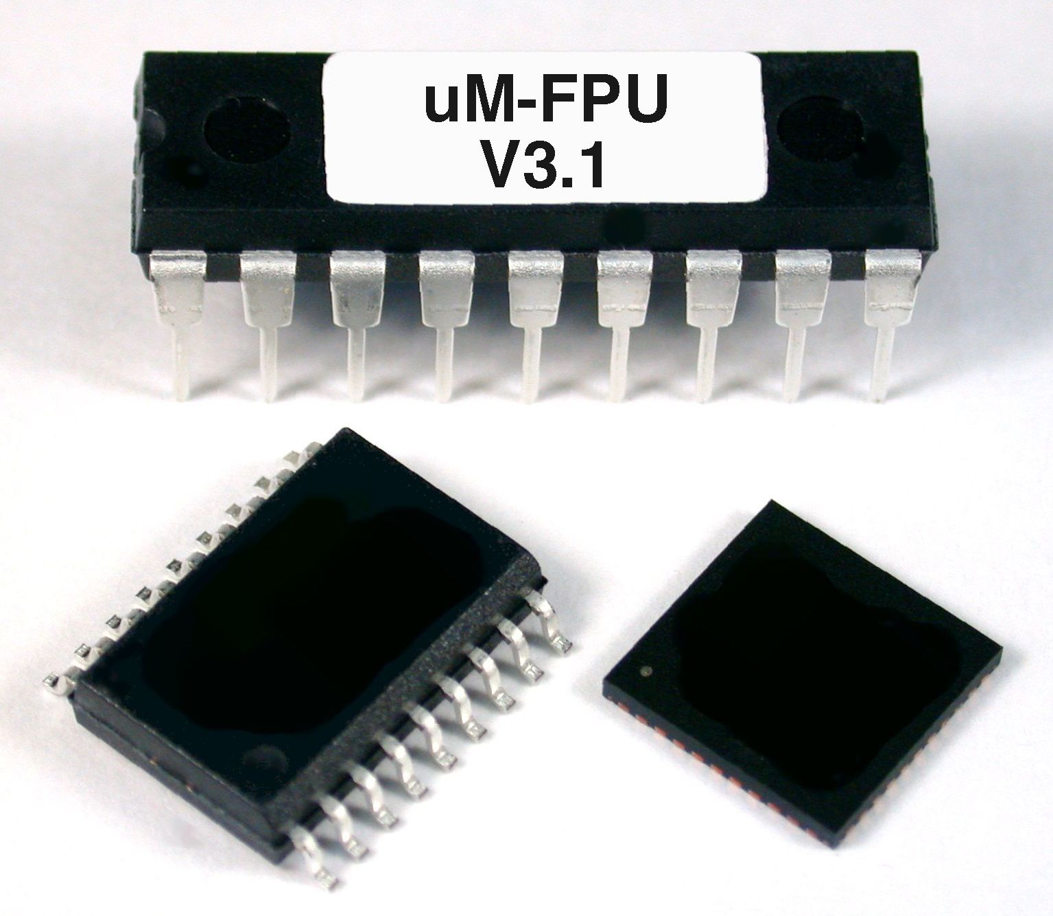
The new uM-FPU V3.1 floating point coprocessor has the speed and features required to support today's advanced microcontroller applications.The uM-FPU V3.1 chip easily interfaces to virtually any microcontroller using an SPI™ or I2C™ interface.
|
|
|
|
Many microcontrollers used in embedded systems lack floating point support, but a wide range of sensors available today require additional computations or data transformation to provide accurate results.
Software math libraries often use large amounts of memory on microcontrollers, particularly as more complex library functions are used. The uM-FPU V3.1 chip offloads this overhead, and provides a comprehensive set of floating point operations, including advanced functions such as FFT, matrix operations and NMEA sentence parsing.
 Advanced operations and fast execution allows the uM-FPU V3.1 chip to outperform comparable software math libraries. It also provides Flash memory and EEPROM for storing user-defined functions and data, and 128 32-bit registers for floating point and integer data.
Development support is provided by the uM-FPU V3 IDE which takes traditional math expressions and automatically produces uM-FPU code targeted for one of the many microcontrollers and compilers supported. The IDE also interacts with the built-in debugger on the uM-FPU V3.1 chip to assist in debugging and testing uM-FPU code.
For a printed summary of uM-FPU V3.1 features, see uM-FPU V3.1 Brochure.
For a more detailed list of uM-FPU V3.1 features, and changes from V3.0, see uM-FPU V3.1 Release Notes .
Suggested Retail Price: $19.95 USD
|
|
|
|
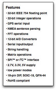
Features
32-bit Floating Point and 32-bit Integer
A comprehensive set of 32-bit floating point and 32-bit integer operations are provided.
See the uM-FPU V3.1 datasheet for details.
User-defined Functions
User-defined functions can be stored in Flash and EEPROM. Flash functions are programmed through the SERIN/SEROUT pins using the uM-FPU V3 IDE. The EEPROM functions can be programmed at run-time. Conditional execution is supported using conditional branch and jump instructions.
Matrix Operations
A matrix can be defined as any set of sequential registers. The MOP instruction provides scalar operations, element-wise operations, matrix multiply, inverse, determinant, count, sum, average, min, max, copy and set operations.
FFT Instruction
Provides support for Fast Fourier Transforms. Used as a single instruction for data sets that fit in the available registers, or as a multi-pass instruction for working with larger data sets.
Serial Input / Output
When not used for debugging, the SERIN and SEROUT pins can be used for serial I/O. For example, SERIN can be used to read data from a GPS, and SEROUT can be used to drive an LCD.
NMEA Sentence Parsing
The serial input can be set to scan for valid NMEA sentences with optional checksum. Multiple sentences can be buffered for further processing.
String Handling
String instructions are provided to insert and append substrings, search for fields and substrings, convert from floating point or long integer to a substring, or convert from a substring to floating point or long integer. For example, the string instructions could be used to parse a GPS NMEA sentence, or format multiple numbers in an output string.
Table Lookup Instructions
Instructions are provided to load 32-bit values from a table or find the index of a floating point or long integer table entry that matches a specified condition.
MAC Instructions
Instructions are provided to support multiply and accumulate and multiply and subtract operations.
A/D Conversion
Two 12-bit A/D channels are provided. The A/D conversion can be triggered manually, through an external input, or from a built-in timer. The A/D values can be read as raw values or automatically scaled to a floating point value. Data rates of up to 10,000 samples per second are supported.
Timers
Timers can be used to trigger the A/D conversion, or to track elapsed time. A microsecond and second timer are provided.
External Input
An external input can be used to trigger an A/D conversion, or to count external events.
Low Power Modes
When the uM-FPU V3 chip is not busy it automatically enters a power saving mode. It can also be configured to enter a sleep mode which turns the device off while preserving register contents. In sleep mode the uM-FPU V3 chip consumes negligible power.
Internal Oscillator
Operates at full speed from internal oscillator. No external components required.
|
|
Pin Diagram and Pin Descriptions |
PDIP-18, SOIC-18 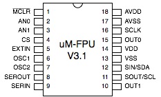 |
| Pin |
Name |
Type |
Description |
| 1 |
/MCLR |
Input |
Master Clear (Reset) |
| 2 |
AN0 |
Input |
Analog Input 0 |
| 3 |
AN1 |
Input |
Analog Input 1 |
| 4 |
CS |
Input |
Chip Select, Interface Select |
| 5 |
EXTIN |
Input |
External Input |
| 6 |
OSC1 |
Input |
Oscillator Crystal (optional) |
| 7 |
OSC2 |
Output |
Oscillator Crystal (optional) |
| 8 |
SEROUT |
Output |
Serial Output, Debug Monitor Tx |
| 9 |
SERIN |
Input |
Serial Input, Debug Monitor Rx |
| 10 |
OUT1 |
Output |
Digital Output 1 |
| 11 |
SOUT
SCL |
Output
Input |
SPI Output, Busy/Ready Status
I2C Clock |
| 12 |
SIN
SDA |
Input
In/Out |
SPI Input
I2C Data |
| 13 |
VSS |
Power |
Digital Ground |
| 14 |
VDD |
Power |
Digital Supply Voltage |
| 15 |
OUT0 |
Output |
Digital Output 0, Busy/Ready Status |
| 16 |
SCLK |
Input |
SPI Clock |
| 17 |
AVSS |
Power |
Analog Ground |
| 18 |
AVDD |
Power |
Analog Supply Voltage |
|
|
|
Documentation |
uM-FPU V3.1 Datasheet
Functional description and hardware specifications.
|
|
uM-FPU V3.1 Instruction Set
Detailed descriptions for each instruction.
|
|
|
Support Software |
| The uM-FPU V3.1 floating point coprocessor is easily interfaced with virtually any microcontroller that provides an SPI or I2C connection. See the Downloads page for a list of available support software. For microcontrollers that are not currently supported, the interface routines can be easily developed using the software for a similar microcontroller as a template for porting the code. |
|
|
|